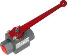
>> 2-Way High
Pressure Ball Valve (Model Code - AHB G - 1/8” to 2”).
DESCRIPTION
Flutec 2-way High pressure Ball Valves are of a compact construction.
- Working temperature depending upon sealing material - 200C to + 2500C
- Easy handling even at high
pressure (switching through 900)
- Working pressure upto 500/1000bar .
- Individual pressure testing ensures safety.
- If the ball valve are to be used for gas, oxygen or any other special application, please give full details when ordering with temparture and pressure.
- Block housing in carbon steel phosphate plated. Other metallic finish on request.
- Are also manufactured in stainless steel & Brass material.
- Are supplied with red powder coated straight aluminium / steel handles.
|
|
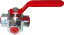
>> 3-Way Ball Valve (Model Code-AHB3K - 1/8” to 2”).
DESCRIPTION
Flutec 3-way Ball Valves are of a compact construction..
- Working temperature depending upon sealing material - 200C to +2500C.
- Working pressure up to 500bar.
- Easy handling even at high pressure (switching through 900).
- Individual pressure testing ensures safety.
- If the ball valve are to be used for gas, oxygen or any other special application, please give full details when ordering with temparture and pressure.
- Block housing in steel chrome plated. Other metallic finish on request.
- Are also manufactured in stainless steel & Brass material.
- Are supplied with red powder coated cranked steel handles.
- Size Range : 1/8" to 2"
|
|
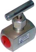
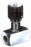
>> NEEDLE VALVE/ SHUT OFF VALVE
DESCRIPTION
Flutec 3-way Ball Valves are of a compact construction.
- Flutec Needle Valves are designed for accurate regulation and positive shut-off in impulse and instrument lines and other small line systems.
- Under pressure upto maximum 1000 bar.
- Needle valves are manufactured for all general application i.e. oil, water, gas, steam and other wide range of fluids.
- Individual pressure testing ensures safety.
- The valves are available in carbon steel, SS304, 316, and Brass with BSP/NPT end connections.
- Size Range : 1/8" to 11/2"
|
|
|
 |
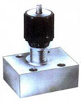
>> Manifold Block
Mounting Ball Valves(Model code - AHP -10 to 38).
DESCRIPTION
Flutec 2-way High pressure Ball Valves are of a compact construction.
- Flutec manifold mounted Ball
Valve for mounting on to valves Block.
- The Ball valve has a milled slot indicating the setting. The valve is positioned by means of stop pin and stop disc.
- Easy handling even at high pressure upto 350bar(switching through 900).
- Individual pressure testing ensures safety.
- Operating temperature- -200C to +2500C depending upon the sealing material.
- If the ball valve are to be used for gas, oxygen or any other special application, please give full details when ordering with temparture and pressure.
- Housing Steel (Standard model phosphate plated, other metallic finish on request).
- Ball - Stainless steel.
- Red powder coated aluminium / steel handles.
- Sizes from AHP 10 to 38.
|
Model
Code |
A |
B |
C |
D |
E |
F |
G |
ØH |
ØJ |
ØK |
ØL |
| AHP 10 |
70 |
55 |
45 |
40 |
- |
55 |
44 |
9.5 |
15 |
14 |
8.4 |
| AHP 16 |
98 |
60 |
55 |
45 |
41.5 |
83 |
58 |
16.0 |
25 |
14 |
8.4 |
| AHP 20 |
117 |
70 |
70 |
51 |
48.5 |
97 |
69 |
20.0 |
30 |
17 |
10.5 |
| AHP 25 |
135 |
80 |
80 |
60 |
57.5 |
115 |
81 |
23.5 |
35 |
17 |
10.5 |
| AHP 32 |
165 |
100 |
100 |
78 |
68.0 |
136 |
96 |
32.0 |
40 |
19 |
13.0 |
|
 |
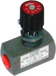
>> Flow Control Valves.
DESCRIPTION
Permits
a simple and accurate control of hydraulic fluid, with increasing
number of turning of the control knob, starting from the closed
position the flow increases evenly. The last turning results in a
complete opening of the flow passage. The flow in the reverse
direction is free. The coloured scale permits a good repetition of
settings and the coloured triangle provides a visible indication of
the flow control valve opening. Increase of the coloured triangle
equals increased flow through the flow control valve. A setscrew is
provided in the side of the knob to lock the flow control valve in
set position to comply with safety standards. |
 |
|
 |
|
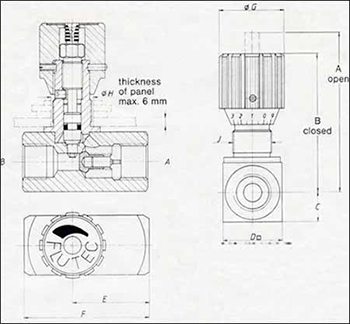 |
| Model Code |
Thread |
A |
B |
C |
D |
E |
F |
G |
H |
J |
SW |
Weight
(kg) |
| TCV-6 |
1/8" |
55 |
50 |
8 |
16 |
26 |
45 |
24 |
13 |
Pg 7 |
- |
0.13 |
| TCV-8 |
1/4" |
72 |
65 |
12.5 |
25 |
33.5 |
55 |
29 |
19 |
Pg11 |
- |
0.30 |
| TCV-10 |
3/8" |
74 |
67 |
15 |
30 |
41 |
65 |
29 |
19 |
Pg11 |
- |
0.45 |
| TCV-12 |
1/2" |
92 |
82 |
17.5 |
35 |
44 |
73 |
38 |
23 |
Pg16 |
- |
0.80 |
| TCV-16 |
3/4" |
106 |
96 |
22.5 |
45 |
57 |
88 |
38 |
23 |
Pg16 |
- |
1.30 |
| TCV-20 |
1" |
145 |
128 |
25 |
50 |
77 |
127 |
49 |
38 |
Pg29 |
19 |
2.40 |
| TCV-25 |
1 1/4" |
150 |
133 |
30 |
60 |
93 |
143 |
49 |
38 |
Pg29 |
19 |
3.50 |
| TCV-30 |
1 1/2" |
155 |
138 |
35 |
70 |
108 |
143 |
49 |
38 |
Pg29 |
19 |
4.60 |
| TCV-40 |
2" |
165 |
148 |
45 |
90 |
130 |
165 |
49 |
38 |
Pg29 |
19 |
7.70 |
|
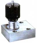
>> Manifold Block Mounting Flow Control Valves - with Check Valve
(Model Code -TCVP 8 to 40)
DESCRIPTION
Flutec manifold
mounted flow control Valve for mounting on to Block. Permits a
simple and accurate control of hydraulic fluid, with increasing
number of turning of the control knob, starting from the closed
position the flow increases evenly. The last turning results in a
complete opening of the flow passage. The flow in the reverse
direction is free. The coloured scale permits a good repetition of
settings and the coloured triangle provides a visible indication of
the flow control valve opening. Increase of the coloured triangle
equals increased flow through the flow control valve. A setscrew is
provided in the side of the knob to lock the flow control valve in
set position to comply with safety
standards.
|
 |
|
|
|
Model
Code |
A |
B |
C |
D |
E |
F |
G |
H |
J |
ØK |
ØL |
ØM |
ØN |
ØP |
| TCVP-8 |
89 |
82 |
63.5 |
50.0 |
30 |
25.5 |
- |
35.0 |
33.5 |
7.0 |
12.7 |
11 |
6.6 |
M18 X 1.5 |
| TCVP-10 |
91 |
84 |
70.0 |
50.0 |
32 |
25.5 |
- |
33.5 |
38.0 |
10.0 |
15.7 |
11 |
6.6 |
M18 X 1.5 |
| TCVP-12 |
113 |
103 |
80.0 |
57.5 |
38 |
30.0 |
- |
38.0 |
44.5 |
13.0 |
18.7 |
11 |
6.6 |
M22 X 1.5 |
| TCVP-16 |
132 |
120 |
104.0 |
70.0 |
45 |
54.0 |
38.0 |
76.0 |
54.0 |
17.0 |
24.5 |
14 |
9.0 |
M22 X 1.5 |
| TCVP-20 |
170 |
153 |
127.0 |
76.5 |
50 |
57.0 |
47.5 |
95.0 |
60.0 |
22.0 |
30.5 |
14 |
9.0 |
M38 X 1.5 |
| TCVP-25 |
175 |
158 |
165.0 |
100.0 |
55 |
79.5 |
60.0 |
120.0 |
76.0 |
28.5 |
37.5 |
18 |
11.0 |
M38 X 1.5 |
| TCVP-30 |
195 |
178 |
186.0 |
115.0 |
75 |
95.0 |
71.5 |
143.0 |
92.0 |
35.0 |
43.5 |
20 |
14.0 |
M38 X 1.5 |
|
>> Flow Control
Valves - without Check Valve
( Model Code -TV 6 to 40).
DESCRIPTION
- Flutec Valves are
designed to provide simple and accurate control of hydraulic
fluids.
- By increasing number of turning
of the control knob, starting from the closed position the
flow increases evenly.
- The last turning results in a
complete opening of the flow passage.
- The coloured scale and coloured
ring in the top of the control knob permits an accurate
repetition of settings and visual indication of the flow
area.
- Increase in the size of the
coloured triangle on the rings corresponds to an increase in
flow area.
- A setscrew is provided in the
side of the knob to lock the flow control valve in set
position to comply with safety standards.
|
 |
|
|
|
| Model Code |
A |
B |
C |
SQ. D |
E |
| TV - 1/4" BSP |
89 |
82 |
48 |
30 |
M18 X 1.5 |
| TV - 3/8" BSP |
91 |
84 |
58 |
32 |
M18 X 1.5 |
| TV - 1/2' BSP |
113 |
103 |
68 |
38 |
M22 X 1.5 |
| TV - 3/4' BSP |
135 |
125 |
78 |
50 |
M22 X 1.5 |
| TV - 1' BSP |
170 |
153 |
100 |
50 |
M38 X 1.5 |
| TV - 1 - 1/4' BSP |
180 |
163 |
108 |
60 |
M38 X 1.5 |
| TV - 1 - 1/2' BSP |
190 |
173 |
108 |
70 |
M38 X 1.5 |
|
>> >> Flow Control Valves - without Check Valve
( Model Code -TV 6 to 40).
DESCRIPTION
- Flutec Valves are
designed to provide simple and accurate control of hydraulic
fluids.
- By increasing number of turning
of the control knob, starting from the closed position the
flow increases evenly.
- The last turning results in a
complete opening of the flow passage.
- The coloured scale and coloured
ring in the top of the control knob permits an accurate
repetition of settings and visual indication of the flow
area.
- Increase in the size of the
coloured triangle on the rings corresponds to an increase in
flow area.
- A setscrew is provided in the
side of the knob to lock the flow control valve in set
position to comply with safety standards.
|
 |
|
|
|
Model
Code |
A |
B |
C |
D |
E |
F |
G |
H |
J |
ØK |
ØL |
ØM |
ØN |
ØP |
| TVP-8 |
79 |
72 |
47.5 |
46.0 |
20 |
25.5 |
- |
35.0 |
33.5 |
7.0 |
12.7 |
11 |
6.6 |
M18 X 1.5 |
| TVP-10 |
84 |
77 |
50.0 |
50.0 |
25 |
25.5 |
- |
33.5 |
38.0 |
10.0 |
15.7 |
11 |
6.6 |
M18 X 1.5 |
| TVP-12 |
99 |
89 |
75.0 |
57.5 |
25 |
30.0 |
- |
38.0 |
44.5 |
13.0 |
18.7 |
11 |
6.6 |
M22 X 1.5 |
| TVP-16 |
113 |
103 |
93.5 |
70.0 |
30 |
54.5 |
38.0 |
76.0 |
54.0 |
17.0 |
24.5 |
14 |
9.0 |
M22 X 1.5 |
| TVP-20 |
165 |
148 |
111.0 |
76.5 |
45 |
57.0 |
47.5 |
95.0 |
60.0 |
22.0 |
30.5 |
14 |
9.0 |
M38 X 1.5 |
| TVP-25 |
165 |
148 |
143.0 |
100.0 |
45 |
79.5 |
60.0 |
120.5 |
76.0 |
28.5 |
37.5 |
18 |
11.0 |
M38 X 1.5 |
| TVP-30 |
170 |
153 |
171.0 |
115.0 |
50 |
95.0 |
71.5 |
143.0 |
92.0 |
35.0 |
43.5 |
20 |
14.0 |
M38 X 1.5 |
|
|